Joe Ødegård, Architect

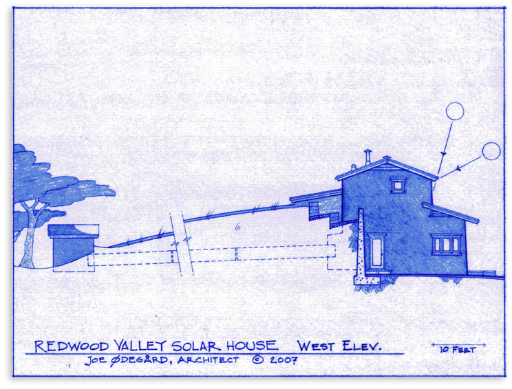
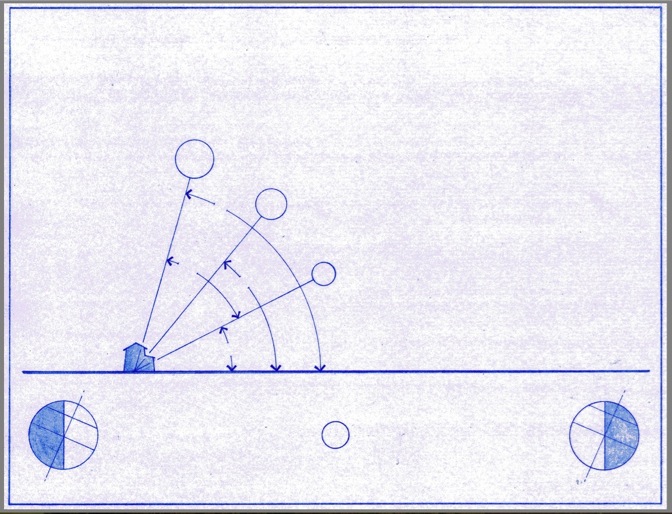
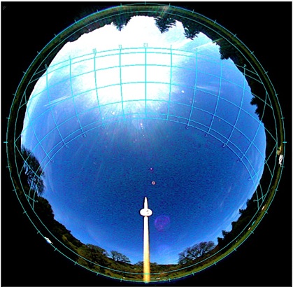
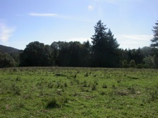
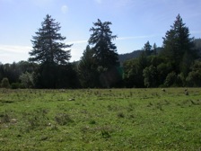
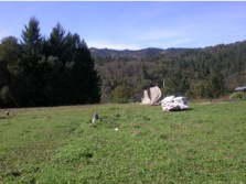
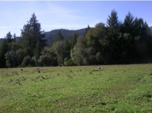
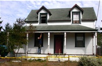
Construction is pending on this house. It is a “passively” heated solar house, and it is also cooled on summer nights with air from a shade forest traveling in a culvert which runs under an earth berm on the north side of the house. The house roof supports 56 amorphous silicon photovoltaic panels generating about 4,760 peak Watts. Water heating is direct solar. The house is designed for a farming couple with children. The fish eye view of the sky at left was used to select this site.


Water heating panels
14 uni solar PVL136,
tot. rated watts 1904

42 uni solar PVL 68,
tot. rated watts 2,856

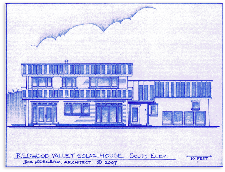
South solar gain windows on both floors
Light colored, reflective patio paving


Summer noon shadow lines from latitude determined roof eaves

Gravel Drive
Water heating panels
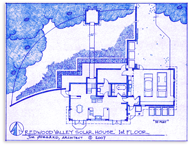
Garage
Workbench
Battery bank
Porch
Living
Kitchen
Dining
Office
Plenum
Pantry


Cantina
Bath
Entry
Step
Patio
Retaining Wall
Gabbions
Earth berm
Cool air culvert
Fan house
“Slot”
(Berm and culvert are longer than shown here)
Earth symbol


Cord wood
Light colored paving
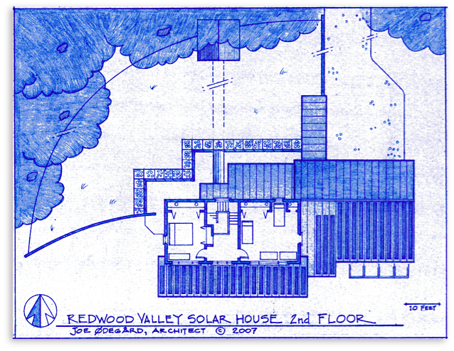
Loft with hot water tank

foam core concrete walls


Shade forest
Gravel drive
Fan house
Patio
Earth berm planted in native grass
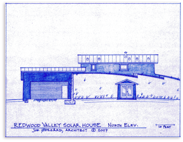
Standing seam metal roof, typical
“Slot”
Gabbions
Shade Forest
Shade Forest
Master
bedroom
Wood stove

Hall
Kid’s bedroom
Buried cool air culvert for night cooling
Water heating panels below

21 Uni solar pvl 68,
at 68 watts each
14 Uni solar pvl 136,
at 136 watts each
Foam core concrete retaining wall, typ.


June 21
Dec. 21
Mar. 21
Noon sun


Earth berm
Cord wood
Gravel Drive
Water heating panels row 1
Water heating panels row 2

For seasonal sun control (house heating), the south eaves are located at the intersection of the winter noon line drawn from the top of the south facing glass, and the summer noon line drawn from the bottom of the south facing glass. Glass location and latitude both affect the eave position.


Photovoltaics are aimed at the summer sun noon angle for max. generation on a yearly average. This angle determines the south facing roof pitch.
Water heating panels are aimed at the equinox sun because there is less need of hot water in the summer.
Winter sun angle determines spacing between rows of water heating panels to avoid shade - out.
Night air vents for summer cooling.


Wood stove backup heating for stretches of cloudy weather


Tubular skylights


Earth berm planted in native grass
Fan House
Retaining Wall
Gravel drive

Gabbions

Standing seam metal roof


Tubular Skylights (5)


June
Dec.
Planted Shade Forest
Fan house
Sol
Summer
Winter
N.
S.
N.
S.


This angle is the same for all latitudes.

Mid Summer noon
Equinox Noon


(Looking East)
HORIZON
This diagram shows the Earth’s tilt of 23º 28’
How Sun Angles work:
• Earth’s tilt relative to its plane of
orbit is 23º 28’.
• To get equinox noon sun altitude,
subtract latitude from 90º (angle 2).
• To get the mid-summer noon sun
altitude, add Earth’s tilt to the
equinox altitude (angle 3).
• To get the mid-winter noon sun
altitude, subtract the Earth’s tilt
from the equinox altitude (angle 1).
These 3 angles are for Redwood Valley, and all other locations at 39º 16’ north latitude.
1
2
3


Retaining Wall

Earth berm planted in native grass
Buried cool air culvert for night cooling


(Berm and culvert are longer than shown here)


• Latitude of Redwood
Valley is 39º 16’ North.
• For other sites use other
latitudes.
Copyright Joe Ødegård Architect 2009


Concrete & tile floor

The rules of thumb for passive solar house
heating are these (for most US climates):
• Have good solar exposure, & face the house south.
• Keep the house volume modest & insulate the house
well, especially the roof and the north side.
• Control air infiltration.
• Stretch the house plan a bit to the east and west.
• Use “heat admitting low-E” glass.
• Put most of the glass on the south side and have the
right amount of it.
• Locate south overhangs exactly to let in all the winter
sun and keep out all the summer sun.
• Have enough heatable mass inside the house so it
heats up slowly, does not get too hot, and cools down
slowly.
• Have a backup heating system for stretches of cloudy
weather.
• Have enough opening windows for flexible
temperature control.
• Have some light colored ground surface in front of
the house to the south, if possible.
There you have it.
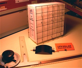
A sample of the foam core and wire wall form, and of the flexible solar cell material which will go on the roof.
This is a “passive” solar house: The house is the solar collector. There are no moving parts, and the components of the system are mostly the components that a house has already — walls, floors, roof, windows and doors, and so forth. There is some extra “thermal mass”, in this case concrete, and it is the correct disposition of these parts in the sunlight that heats the house for free. Passive solar is by far the cheapest way to collect solar energy, but you have to plan for it before you build.
The heated floor area of this house is 1,480 square feet, modest enough that the sun can heat the house on clear winter days. Really large buildings tend to be dominatd by internal conditions & are not as adaptable to solar heating.
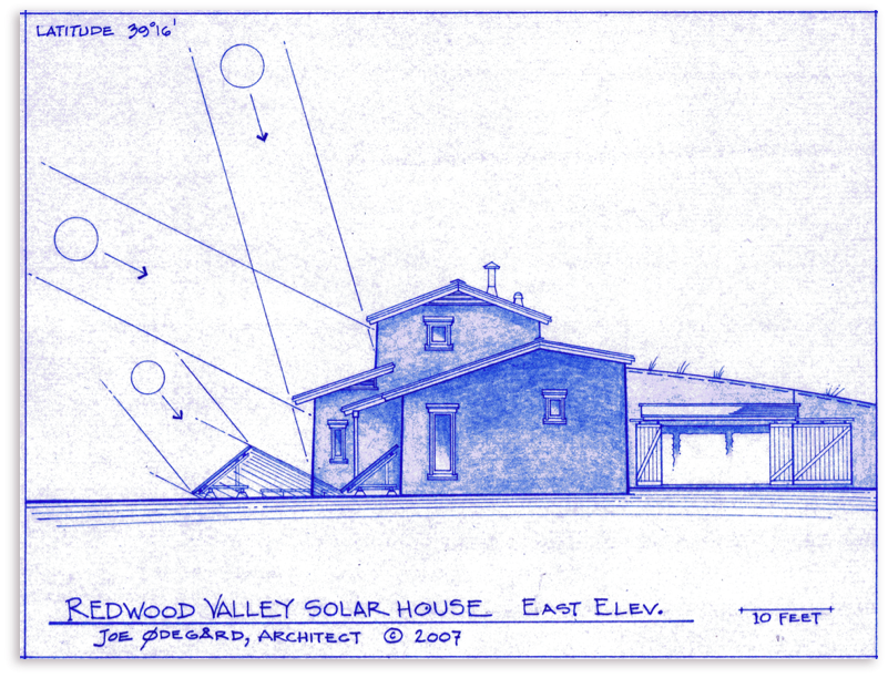
To the right you can see the noontime sun angles that determine many of the shapes of this house. Winter and Summer sun angles vary according to latitude. Passive solar houses are creatures of the middle latitudes: in the far north there is not enough winter sun for effective solar heating, & in the tropics you do not need any more heat.
There is a chart explaning sun angles at the bottom of this page, showing how to calculate the sun angles for your own latitude.
Most of the exterior walls of the Redwood Valley Solar House are pneumatically placed concrete over a foam and wire core. This sandwich construction - the foam is in the middle - provides great strength, insulation, and the “thermal mass” for the interior of the house. Here is the web address with information about this system, made by the “Tri-D” company:
The photovoltaic cells on the roof (see below) are amorphous thin film flexible cells and they are glued directly to the metal roofing pans. You can see these on the web at:


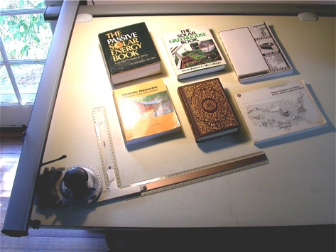
Here are some excellent books. Left to right, top to bottom, they are:
• The Passive Solar Energy Book, Professional Edition, Mazria, 1979.
• The Solar Greenhouse Book, Ed. by James McCullagh, 1978
• Passive Solar Handbook, by the California Energy Commission. 1980
• Alternative Construction, Ed. by L. Elizabeth & C. Adams. 2005
• The Sun and the Welfare of Man, C.G. Abbot. 1929
• Regional Guidlines for Building Passive Energy Conserving Homes,
U.S. Dept. of Housing & Urban Development & AIA Research Co. 1980
Please feel free to E mail me if you have questions about these books.
To see the complete heat calculations for the Redwood Valley Solar House, click on the chart.

See the sun angle chart at the bottom of this web page
Cooling exits for night air (4 total)


Cool air enters here


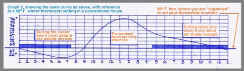
Remotre fan house for summer cooling. A slow speed fan moves cool night air to the house through the cool buried culvert. This air removes some of the heat of the previous day as it exits the hous’s eave vents. A “swamp cooler” or a ground connected heat pump could also be located in the fan house. Fan house equipment is powered by the photovoltaic panels on the house roof.


Plenum

Gabbion note: in the first design for this house the earth berm touched the north wall. But upon the advice of Prof. Ken Haggard, solar pioneer (under whom I studied) I used gabbions (wire rock baskets) to terminate the earth berm before the wall. Prof. Haggard wrote some of the chapters in some of the books I reference at the bottom of thiis web page.


Cool air enters here


Some notes on the electrical system:
A preliminary sizing of the photovoltaic system is as follows:
• Probable KWH per year at the site: 6,450.
• Probable KWH per day: about 18.
• Batteries to cycle 50% per day, so 18x2 = 36 KWH required.
• With a 48 volt system, 36KWH÷48V = 750 amp hours req.
• This equals two strings of “L16” batteries at 8 batteries per
string, at 350 - 400 amp hours per string.
• Total battery cost will be around $4,800.
• The inverters will be 2 “Outback Power System”
GVFX 3648.
I will post updated information here as it comes in.
This preliminary sizing was done with California Solar Initiative size estimation page for photovoltaic systems, on the web at:
Thanks to Bruce Erickson of Mendocino Solar Service for help with this preliminary estimate:


South
East
West
Excellent sun exposure
in every
season


The sky is visible from East to West right down almost to the horizon, which makes this an excellent solar site.


Contact:

Home

Passive solar designs always get top priority in my office.